Beginners Guide to Design for 3D Printing Course

If you are new to 3D Design with Fusion 360 and new to desktop 3D Printing it can be an overwhelming task! You have to not only figure out how to design, but you also have to understand some of the fundamentals of design for 3D Printing.

We have just released a course on Learn Everything About Design to help with this.

In our newest course we will walk you basics of 3D printing, Materials, and Designing. We will walk through the design and print of a desk clip to organize cables, a cell phone amplifier stand, and an assembly for launching toy cars.

You will learn some basics such as how to design without supports, how to identify problems while slicing, and how to recognize problematic design geometry.

For the course we are using a Creality Ender printer, but nearly all desktop 3D printers will be large enough for the designs.

The first topic of discussion is around basic materials that are available. Helping you decide between PLA, PETG, ABS, and TPU as some of the more common options. Most printers will handle PLA and that is usually the first material that will get printed.

We will also explore using Fusion 360 as a slicer before moving into the slicer that comes from Creality. Since we are looking at default and basic settings, any printer and slicer will work just fine. We won’t be doing much customization of settings.

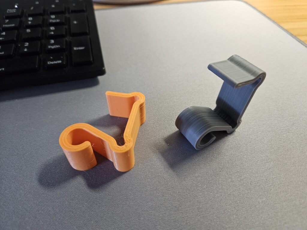
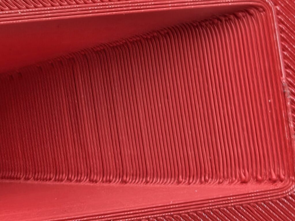
The desk clip design is a simple and satisfying thing to start with. You can customize it for your own needs but follow the same design principles of a consistent wall thickness to simplify the 3D print layers. Even though we aren’t designing for injection molding, keeping a consistent wall thickness and working in multiples of the trace width of a 3D printer can produce stronger designs, even in PLA. When a design is not a consistent wall thickness you will end up with gaps in the traces that need to be filled back in or have Infill. This is generally a weaker approach depending on the application.

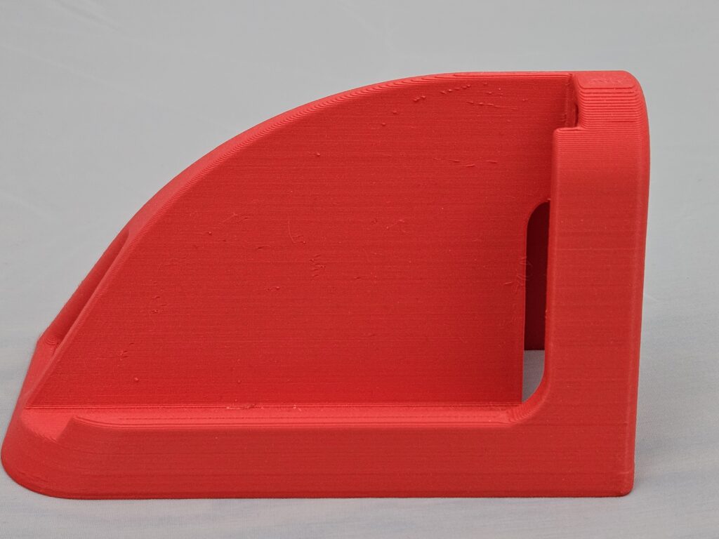
After the desk clip we move to designing a cell phone amp. We don’t need a detailed cell phone model, just basic measurements with a ruler for the size and location of the speaker. Using this we can position the model in 3D and begin designing the stand. The emphasis of this design will be no supports. Each time a 3D print requires supports this adds more time when post processing. Some cases the supports will break off nicely, but in others they will become difficult to remove and often times impossible. We will look at the use of geometry such as diamonds and triangles to build a chamber that doesn’t require impossible to remove supports. This design will also help us better understand how to modify a design to better enable support-less printing and how curvature will affect the final appearance of a design.

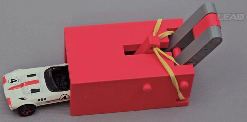
The last design will be an assembly used to launch a toy car. Working with 3D printed assemblies can be very tricky. We will learn how to deal with components and motion in Fusion, identify some assembly tips and techniques and highlight areas of design that are not well suited for desktop 3D printing such as small snap features.

After completing all 3 designs we hope that you will have a better understanding of working in Fusion 360 and how to design for desktop 3D Printing. It is important to note that we are taking an entry level approach to this topic. You can work with extremely complex designs but some of the core concepts will always remain.

How To Scan A Car Fender With The Revopoint Miraco 3D Scanner

The Revopoint Miraco is a great option when you need to scan large objects because everything you need is in a single unit! You can capture and process a scan without needing to be hooked up to a laptop. Scanning anything or in hard to reach areas while tethered to a computer or the wall can make a difficult task even more challenging.

Check out the Revopoint Miraco on kickstarter until Nov. 30th https://revo.ink/3rJAOoB

With our latest YouTube video we walk through the entire process from prepping the fender with Scan Spray, to every setting used, and how to process the scans once complete.

Scanning anything can be a daunting task and the old adage of Garbage In Garbage Out holds true. So before any scan starts you have to clean and prep your area. For a shiny car fender this means removing trim details you don’t need and preparing it with a spray. We use feature tracking on my Mitsubishi Starion and it works very well. Removing the wheel and opening the hood helps access to mounting areas for the fender.

Once your part is ready to be scanned you will need to set up the scanner to capture the best data possible. When dealing with white objects or objects with a consistent surface like the scan spray it is often best to set the exposure manually to avoid areas of over exposure seen as red in the depth camera preview. This is true for consumer IR Structured Light scanners, but many other scanners as well. A preview like this might look ok, but the red areas will be over-exposed and lead to scan quality issues often seen as points floating above the actual surface of the part.

For the white scan spray on the white car I used a final exposure setting of 1 while scanning in far mode. The Miraco scanner can toggle between near and far mode during a single scan allowing the capture of small features on larger objects. If you happen to use this feature be sure to double check your distances and exposures as you go.

Once the exposure is set, validate the scan settings to be used. These settings will changes as the Miraco receives updates, but to get the best results we will use Feature tracking with High Accuracy and a General object type. These settings all affect how many frames are captured, the density of the points, and the tracking inside the software. I personally found with a boxy fender shape the scanner had more trouble with tracking capturing at 16fps than using High Accuracy.

With the project settings ready it is time to slowly walk around your object trying to keep the scanner at a good distance and orientation. With Far scanning on the Miraco that is generally between 600-1200mm away from the fender. Maintaining a perpendicular orientation is also a critical aspect of 3D scanning. As the angle changes relative to the object the data bouncing back to the scanner becomes less accurate. It is extremely important to maintain proper angles as you move around to get the best data.

With larger objects I generally try to capture as much detail in a single scan as possible, but the more points captured the longer the processing will take. If you need to capture data in multiple scans, ensure there is enough detail in each scan that will overlap and allow them to be properly aligned and merged. For this fender I captured the main fender as a single scan, but went back in a second scan to pick up more detail in the wheel well.

Bring the data back to a computer for more processing. While the Miraco can do it all, having more PC resources and a mouse will certainly help. The process starts with Fusion, which is the merge of points in the raw scan data. For something large but with detail like a car fender it is often best to put this number as low as it will go. For the fender it was .57mm, so any points closer than that will get merged together. This number will change based on your scan settings and raw data.

The data will look really messy still but it can be cleaned up. If you are working with multiple scans I find its best to use Fusion and Isolation on each scan before attempting to merge them. Isolation will help easily remove extra points based on their size relative to the main conglomeration of points.

Applying an isolate will delete and remove anything in red. This alone makes a big difference but the detail work of manually selecting and removing areas of the scan that aren’t needed is likely the most time consuming part of this process.

Once each of your scans are cleaned up with Fusion, Isolation, and some manual removal it is time to merge them. They are still points which will allow for additional processing as needed. Because these scans were done based on features we will use feature alignment. Note that you can do additional clean up and re-merge the points if you wish, but pay close attention to details and how they overlap. Generating a model here will make a copy of both sets of points.

With both scans merged return to do some additional isolate and overlap detection. Overlap detection and cleanup will make a HUGE difference in your end results. Move the overlap slider around to smaller numbers around your Fusion amount, then up to a larger value. Once all the overlap has been removed you can use smoothing. With a car fender use a larger strength value, around 10-12, with a lower times value, around 3 or 4. This will allow the points to move more relative to their position but will have less affect on the sharper edges. When it all looks good its time to generate a mesh.

Mesh settings, much like Fusion settings, will vary based on your scan data and scan settings. Using the smallest number here will produce a more dense mesh. Everything can be undone so play around with numbers and see what gives you the best result. For me the smallest value gives the most detail. When a mesh is generated you can check for isolation to make sure no small parts are left before using smoothing if needed. Again be careful here not to use a larger number of times as you will start to lose detail. When you are happy you can export your mesh to your CAD program using an appropriate format like OBJ.

You can do additional mesh processing in CAD to “lighten” the mesh if needed. This mesh was 1.7million facets which can be a little hard on a system, but still doable. You wouldn’t want an entire car scan where each part had this much detail.

You can now use the mesh in your design! If you want to take a look at this scan you can download it as a Fusion 360 or intermediate CAD format. https://a360.co/47bGLtR

Revopoint Miraco 3D Scanner!

RevoPoint reached out after the success of the INSPIRE 3D scanner on kickstarter and asked if I would review the Miraco. This 3D scanner is packed with some unique features that set it apart from the rest of the hobby scanner offerings.

I will be doing some more videos with this in the near future but click on the image above to check out the initial review on our YouTube Channel.

If you want to check it out on kickstarter go here https://revo.ink/3rJAOoB

The rough rundown. The Miraco is a self-contained scanner. You can capture and process the points and mesh on the large touch screen. It has a built in 2.4gHz multi-core processor with 16 or 32Gb ram. It also includes over 200gigs of available memory and a 48mega pixel rgb camera for texture/color data. This unit is essentially the combination of the Revopoint Mini and Range/Inspire into a single hand-held unit.

We will be doing some head to head scans in the future with this, the Inspire, some Creality scanners and Shining.

Site Updates

We are working on reconfiguring the site. removing dead links and structuring it with more information, links, and content.

CADucator.com is still under construction

There is lots of great content on the site so have a look around, but know we are still working on things. Please leave a comment or reach out to us a support@caducator.com if something is wrong with the site or if you have a request.